Turtlebot3 Visual Servoing using ROS and Python


Introduction
Visual servoing is a control method that uses visual feedback from cameras to guide the movement of a robot. It involves continuously adjusting the robot’s joint angles based on the difference between its current visual input and a desired target image. In other words, the robot uses visual information to guide its movements in real time.
Motivation
There are several reasons why visual servoing might be used on a mobile robot. Some potential benefits of using visual servoing on a mobile robot include the following:
- Visual servoing allows a robot to quickly and accurately move to a specific location or perform a specific task based on visual feedback.
- Visual servoing can be used for real-time navigation and obstacle avoidance.
- Visual servoing can be used for object recognition.
- Visual servoing can be used in environments where other types of feedback, such as tactile or force feedback, are not available or reliable.
Overall, visual servoing is a powerful control method that allows robots to quickly and accurately move and interact with their environments based on visual information.
Problem Statement
Design a control system for a mobile robot that uses visual servoing to navigate from point A to point B while avoiding obstacles in its path. The control system should be able to take the desired target image as input and use visual feedback from the camera to continuously adjust the robot’s movements in real time to reach the target location while avoiding obstacles.
Objectives
The goal of the project is to control a robot using a camera fixed on the top of the environment using hand-to-eye visual servo system. The main purpose is to navigate the robot via this camera to the given target point, avoiding obstacles, and parking the robot at a specified pose.
Methodology
Camera Calibration
Camera should be calibrated in order to get the intrinsic parameters of the camera, as they are needed in order to use Aruco Marker pose detection. We have used the camera_calibration package provided by ROS to successfully calibrate the camera.
To get an image from the camera, we have used the ueye_cam package in ROS.
Aruco Marker Detection and Pose Estimation
To detect the Aruco markers at the current and target positions, we subscribe to the /camera/image_raw ROS topic to receive the image. We then crop the image according to the ROI parameters obtained using the calibration file and undistort the image using the OpenCV function cv2.undistort.
Obstacle Detection
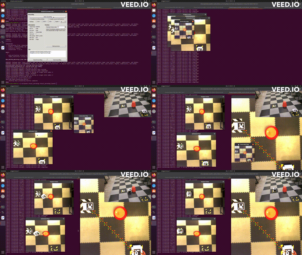
The obstacle detection module uses the input image and slices it into boxes of a size equal to the robot’s size. This way, we have an array with all the possible moves that the robot can achieve. Obstacles are marked with red boxes in the image, and the robot is programmed not to move where there are obstacles.
Path Planning
Using the obstacle map array, the path planning module calculates the shortest path the robot should take to reach the target. This is a graph-based algorithm that uses heuristics for better performance.
Robot Control System
The control system for the mobile robot is based on the kinematics of a two-wheel differential robot. The control system calculates the alpha (α) angle and distance rho (ρ) between the current and target positions, allowing the robot to move effectively.
Calculate beta (β) Euler angle
The project also includes calculating the beta (β) Euler angle to fix the final angle of the robot in respect to the target pose.
Results and Discussion
Running the Package
To run the project, follow these steps:
- Launch the camera using
roslaunch ueye_cam rgb8.launch. - Connect to the Turtlebot over SSH.
- On the Turtlebot, launch
roslaunch turtlebot3_bringup turtlebot3_robot.launch. - On the remote computer, launch the implementation with
roslaunch visual_servoing visual_servoing.launch.
Experimental Results
Results obtained during the project show that the algorithm efficiently devises the shortest path to reach the target by using the A-Star path planning algorithm. The system is capable of navigating both with and without obstacles.
Conclusion
This project provided valuable insights into visual servoing and its application on a real-world problem with a mobile robot. The integration of ROS and the development of a custom